The documentation set for this product strives to use bias-free language. For the purposes of this documentation set, bias-free is defined as language that does not imply discrimination based on age, disability, gender, racial identity, ethnic identity, sexual orientation, socioeconomic status, and intersectionality. Exceptions may be present in the documentation due to language that is hardcoded in the user interfaces of the product software, language used based on RFP documentation, or language that is used by a referenced third-party product. Learn more about how Cisco is using Inclusive Language.
This document provides details about configuring Parallel Redundancy Protocol (PRP) on the Cisco Industrial Ethernet 4000 Series, Cisco Industrial Ethernet 4010 Series, and Cisco Industrial Ethernet 5000 Series switches.
PRP is supported on multiple IE platforms, and PRP feature support may vary by platform. For details, refer to Feature History. Be sure to use the configuration guide for your IE platform.

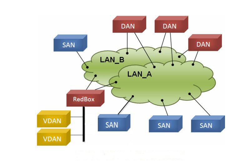
Parallel Redundancy Protocol (PRP) is defined in the International Standard IEC 62439-3. PRP is designed to provide hitless redundancy (zero recovery time after failures) in Ethernet networks. To recover from network failures, redundancy can be provided by network elements connected in mesh or ring topologies using protocols like RSTP, REP, or MRP, where a network failure causes some reconfiguration in the network to allow traffic to flow again (typically by opening a blocked port). These schemes for redundancy can take between a few milliseconds to a few seconds for the network to recover and traffic to flow again. PRP uses a different scheme, where the end nodes implement redundancy (instead of network elements) by connecting two network interfaces to two independent, disjointed, parallel networks (LAN-A and LAN-B). Each of these Dually Attached Nodes (DANs) then have redundant paths to all other DANs in the network. The DAN sends two packets simultaneously through its two network interfaces to the destination node. A redundancy control trailer (RCT), which includes a sequence number, is added to each frame to help the destination node distinguish between duplicate packets. When the destination DAN receives the first packet successfully, it removes the RCT and consumes the packet. If the second packet arrives successfully, it is discarded. If a failure occurs in one of the paths, traffic continues to flow over the other path uninterrupted, and zero recovery time is required. Non-redundant endpoints in the network that attach only to either LAN-A or LAN-B are known as Singly Attached Nodes (SANs). A Redundancy Box (RedBox) is used when an end node that does not have two network ports and does not implement PRP needs to implement redundancy. Such an end node can connect to a RedBox, which provides connectivity to the two different networks on behalf of the device. Because a node behind a RedBox appears for other nodes like a DAN, it is called a Virtual DAN (VDAN). The RedBox itself is a DAN and acts as a proxy on behalf of its VDANs.
The IE 4000, IE 4010, and IE 5000 switches implement RedBox functionality using Gigabit Ethernet port connections to each of the two LANs.
Traffic egressing the RedBox PRP channel group can be mixed, that is, destined to either SANs (connected only on either LAN-A or LAN-B) or DANs. To avoid duplication of packets for SANs, the switch learns source MAC addresses from received Supervision frames for DAN entries and source MAC addresses from non-PRP (regular traffic) frames for SAN entries and maintains these addresses in the node table. When forwarding packets out the PRP channel to SAN MAC addresses, the switch looks up the entry and determines which LAN to send to rather than duplicating the packet.
A RedBox with VDANs needs to send supervisory frames on behalf of those VDANs. For traffic coming in on all other ports and going out PRP channel ports, the switch learns source MAC addresses, adds them to the VDAN table, and starts sending Supervisory frames for these addresses. Learned VDAN entries are subject to aging.
You can add static entries to the node and VDAN tables as described in Adding Static Entries to the Node and VDAN Tables. You can also display the node and VDAN tables and clear entries. See Verifying Configuration and Clearing All Node Table and VDAN Table Dynamic Entries.
Precision Time Protocol (PTP) can operate over Parallel Redundancy Protocol (PRP) on IE 4000, IE 4010, and IE 5000 switches. PRP provides high availability through redundancy for PTP. For a description of PTP, see Precision Time Protocol Software Configuration Guide for IE 4000, IE 4010, and IE 5000 Switches.
The PRP method of achieving redundancy by parallel transmission over two independent paths (see Information About PRP) does not work for PTP as it does for other traffic. The delay experienced by a frame is not the same in the two LANs, and some frames are modified in the transparent clocks (TCs) while transiting through the LAN. A Dually Attached Node (DAN) does not receive the same PTP message from both ports even when the source is the same. Specifically:
Previously, PTP traffic was allowed only on LAN-A to avoid the issues with PTP and parallel transmission described above. However, if LAN-A went down, PTP synchronization was lost. To enable PTP to leverage the benefit of redundancy offered by the underlying PRP infrastructure, PTP packets over PRP networks are handled differently than other types of traffic. The implementation of the PTP over PRP feature is based on the PTP over PRP operation detailed in IEC 62439-3:2016, Industrial communication networks - High availability automation networks - Part 3: Parallel Redundancy Protocol (PRP) and High-availability Seamless Redundancy (HSR). This approach overcomes the problems mentioned above by not appending an RCT to PTP packets and bypassing the PRP duplicate/discard logic for PTP packets.
The following figure illustrates the operation of PTP over PRP.
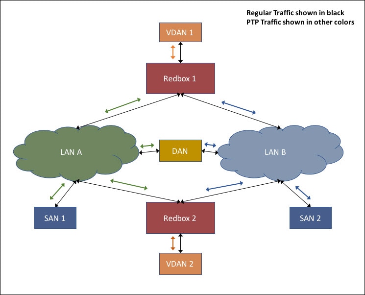
In the figure, VDAN 1 is the grandmaster clock (GM). Dually attached devices receive PTP synchronization information over both their PRP ports. The LAN-A port and LAN-B port use a different virtual clock that is synchronized to the GM. However, only one of the ports (referred to as SLAVE) is used to synchronize the local clock (VDAN 2 in the figure). While the LAN-A port is the SLAVE, the LAN-A port’s virtual clock is used to synchronize VDAN-2. The other PRP port, LAN-B, is referred to as PASSIVE_SLAVE. The LAN-B port’s virtual clock is still synchronized to the same GM, but is not used to synchronize VDAN 2.
If LAN-A goes down, the LAN-B port takes over as the SLAVE and is used to continue synchronizing the local clock on RedBox 2. VDAN 2 attached to RedBox 2 continues to receive PTP synchronization from RedBox 2 as before. Similarly, all DANs, VDANs and Redboxes shown in the figure continue to remain synchronized. Note that for SANs, redundancy is not available, and in this example, SAN 1 will lose synchronization if LAN-A goes down.
Due to the change, VDAN 2 may experience an instantaneous shift in its clock due to the offset between the LAN-A port’s virtual clock and the LAN-B port’s virtual clock. The magnitude of the shift should only be a few microseconds at the most, because both clocks are synchronized to the same GM. The shift also occurs when the LAN-A port comes back as SLAVE and the LAN-B port becomes PASSIVE_SLAVE.
The GM can be located in a PTP over PRP topology as one of the following:
The GM cannot be a SAN attached to LAN-A or LAN-B, because only the devices in LAN-A or LAN-B will be synchronized to the GM.
PTP over PRP does not require configuration beyond how you would normally configure PTP and PRP separately, and there is no user interface added for this feature. The difference is that prior to the PTP over PRP feature, PTP worked over LAN_A only; now it works over both LANs. Before implementing PTP over PRP, refer to Guidelines and Limitations.
The high-level workflow to implement PTP over PRP in your network is as follows:
The following table summarizes PTP over PRP support for the various PTP profiles and clock modes. In unsupported PTP profile/clock mode combinations, PTP traffic flows over LAN-A only. LAN-A is the lower numbered interface. See PRP Channels for PRP interface numbers.
PRP RedBox type as per IEC 62439-3
The switch plays the role of a RedBox in PRP networks. This section describes the types of PRP RedBoxes supported for PTP over PRP as defined in IEC 62439-3.
In the configuration shown below, two RedBoxes (for example, M and S) are configured as Boundary Clocks (BCs) that use the End-to-End delay measurement mechanism and IEEE1588v2 Default Profile. The Best Master Clock Algorithm (BMCA) on RedBox M determines port A and port B to be MASTER. The PTP protocol running on Redbox M treats both ports A and B individually as MASTER ports and sends out Sync and Follow_Up messages individually on both the ports.
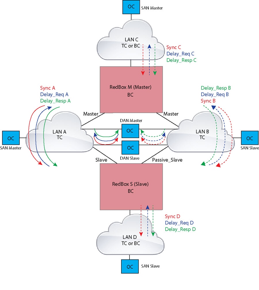
On Redbox S, the regular BMCA operation determines port A to be a SLAVE and port B to be PASSIVE. However, with the knowledge that ports A and B are part of the same PRP channel, port B is forced into PASSIVE_SLAVE state. Port A and Port B on Redbox S operate as follows:
The following figure shows an example where Redbox M and Redbox S are configured to run in Power Profile as Boundary Clocks that use Peer-to-Peer (P2P) delay measurement mechanism. In this example, the GM is the ordinary clock attached through LAN C. All the clocks are configured to run Peer-to-Peer Delay measurement and the peer delay is regularly calculated and maintained on every link shown in the figure.
The BMCA on Redbox M determines ports A and B to be MASTER. The PTP protocol running on Redbox M treats both ports A and B individually as MASTER ports and sends out Sync and Follow_Up messages individually on both the ports.
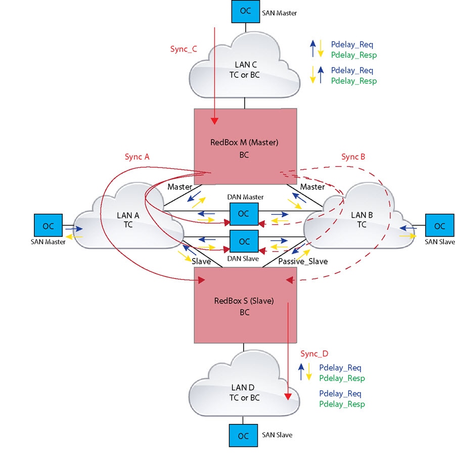
On Redbox S, the regular BMCA operation determines port A to be SLAVE and port B to be PASSIVE. However, with the knowledge that ports A and B are part of the same PRP channel, port B is forced into PASSIVE_SLAVE state. Port A and Port B on Redbox S operate as follows:
The following figure shows an example where Redbox M and Redbox S are configured to run in Power Profile mode as Transparent Clocks. In this example, the GM is the ordinary clock attached through LAN C. All the clocks are configured to run Peer-to-Peer Delay measurement and the peer delay is regularly calculated and maintained on every link shown in the figure.
Redbox M and Redbox S run BMCA even though it is not mandatory for a P2P TC to run BMCA. On Redbox M, the BMCA determines ports A and B to be MASTER. Redbox M forwards all Sync and Follow_Up messages received on port C out of ports A and B.
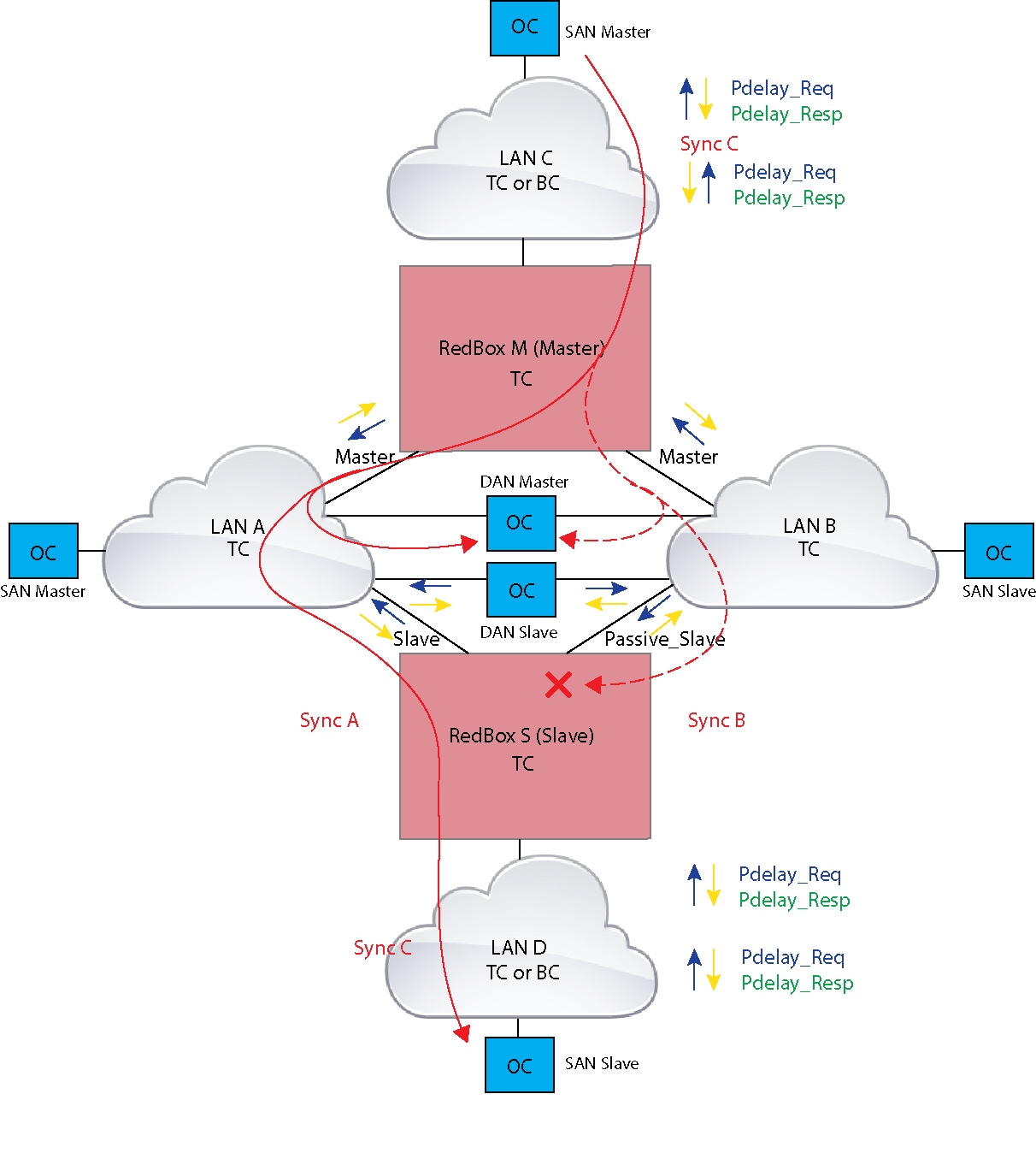
On Redbox S, port A is determined to be SLAVE and port B to be PASSIVE_SLAVE as described earlier. Port A and Port B on Redbox S operate as follows:
Failures in LAN-A and LAN-B are detected and handled in the same way for all Redbox types described in PRP RedBox Types.
Using the example shown in PRP Redbox as DATC with P2P with the GM as a SAN in LAN C, a failure in LAN-A or LAN-B pertaining to PTP can occur due to the following reasons:
These events result in PTP Announce Receipt Timeout on Redbox S, which triggers the BMCA calculation. Refer to section 7.7.3.1 of the IEEE 1588v2 standard for details on Announce Receipt Timeout.
The BMCA, once invoked, changes the state of the PASSIVE_SLAVE port to SLAVE and SLAVE to PASSIVE_SLAVE or PASSIVE or FAULTY. The state changes are done atomically to avoid transient cases where there are two SLAVE ports or two PASSIVE_SLAVE ports.
Redbox S now synchronizes to the GM over the new SLAVE port. The change to synchronization should be quick and seamless, unless the delays experienced by PTP packets on the two LANs are very different or if there are some non-PTP devices in the LANs.
The SAN Slave in LAN D also sees this shift in the timing from Redbox S and needs to converge to the new clock. This is similar to a GM change event for this clock, but as mentioned earlier, the change is usually seamless.
All releases and FPGA support basic PRP for IE 4000, IE 4010 and IE 5000 switches.
However, node table support and automatic learning of source MAC addresses in the VDAN table require the following releases and FPGA versions:
IE4000#sh ver | incl FPGA Backplane FPGA version : 0.37 IE4000#
show prp channel detail PRP-channel listing: -------------------- PRP-channel: PR1 ------------ Layer type = L3 Ports: 2 Maxports = 2 Port state = prp-channel is Inuse Protocol = Disabled Ports in the group: 1) Port: Gi1/17 Logical slot/port = 1/17 Port state = Inuse Protocol = Enabled 2) Port: Gi1/18 Logical slot/port = 1/19 Port state = Inuse Protocol = Enabled
switch(config)#int gi 1/3 switch(config-if)#shut %Interface GigabitEthernet1/3 is configured in PRP-channel group, shutdown not permitted!
On IE 4010, although the capability exists for PRP to allow member ports to be shut down, we do not recommend this option since it is not supported.
show prp channel 2 detail PRP-channel: PR2 ------------ Layer type = L2 Ports: 2 Maxports = 2 Port state = prp-channel is Inuse Protocol = Enabled Ports in the group: 1) Port: Gi1/3 Logical slot/port = 1/3 Port state = Inuse Protocol = Enabled 2) Port: Gi1/4 Logical slot/port = 1/4 Port state = Not-Inuse (link down) Protocol = Enabled
You can use the show ptp port command to verify PTP over PRP configuration. In the command output, the LAN_B port may be displayed as “PASSIVE_SLAVE”.
LED Display mode PRP is disabled.
To create and enable a PRP channel and group on the switch, follow these steps:
The following example is based on the IE 4000. Adjust the interface utilized based on the earlier information.
Enter global configuration mode:
Assign two Gigabit Ethernet interfaces to the PRP channel group:
Use the no interface prp-channel 1 | 2 command to disable PRP on the defined interfaces and shut down the interfaces.
You must apply the Gi 1/1 interface before the Gi1/2 interface. So, we recommend using the interface range command. Similarly, you must apply the Gi1/3 interface before the Gi1/4 interface.
(Optional) For Layer 2 traffic, enter switchport . (Default):
For Layer 3 traffic, enter no switchport .
(Optional) Set a non-trunking, non-tagged single VLAN Layer 2 (access) interface:
switchport mode access
(Optional) Create a VLAN for the Gi1/1-2 interfaces:
switchport access vlan
Only required for Layer 2 traffic.
(Optional) Disable Precision Time Protocol (PTP) on the switch:
PTP is enabled by default. You can disable it if you do not need to run PTP.
Disable loop detection for the redundancy channel:
Disable UDLD for the redundancy channel:
udld port disable
Enter sub-interface mode and create a PRP channel group:
prp-channel-group prp-channel group
prp-channel group—Value of 1 or 2
The two interfaces that you assigned in step 2 are assigned to this channel group.
The no form of this command is not supported.
Bring up the PRP channel:
Specify the PRP interface and enter interface mode:
interface prp-channel prp-channel-number
prp-channel-number—Value of 1 or 2
Configure bpdufilter on the prp-channel interface:
spanning-tree bpdufilter enable
Spanning-tree BPDU filter drops all ingress/egress BPDU traffic. This command is required to create independent spanning-tree domains (zones) in the network.
(Optional) Configure LAN-A/B ports to quickly get to FORWARD mode:
spanning-tree portfast edge trunk
This command is optional but highly recommended. It improves the spanning-tree convergence time on PRP RedBoxes and LAN-A and LAN-B switch edge ports. It is also highly recommended to configure this command on the LAN_A/LAN_B ports directly connected to a RedBox PRP interface.
This example shows how to create a PRP channel on an IE 4000 switch, create a PRP channel group, and assign two ports to that group.
switch# configure terminal switch(config)# interface range GigabitEthernet1/1-2 switch(config-if)# no keepalive switch(config-if)# udld port disable switch(config-if)# prp-channel-group 1 switch(config-if)# no shutdown switch(config-if)# spanning-tree bpdufilter enable
This example shows how to create a PRP channel with a VLAN ID of 2.
switch# configure terminal switch(config)# interface range GigabitEthernet1/1-2 switch(config-if)# switchport switch(config-if)# switchport mode access switch(config-if)# switchport access vlan 2 switch(config-if)# no ptp enable switch(config-if)# no keepalive switch(config-if)# udld port disable switch(config-if)# prp-channel-group 1 switch(config-if)# no shutdown switch(config-if)# spanning-tree bpdufilter enable
This example shows how to create a PRP channel on a switch configured with Layer 3.
switch# configure terminal switch(config)# interface range GigabitEthernet1/1-2 switch(config-if)# no switchport switch(config-if)# no ptp enable switch(config-if)# no keepalive switch(config-if)# udld port disable switch(config-if)# prp-channel-group 1 switch(config-if)# no shutdown switch(config-if)# spanning-tree bpdufilter enable switch(config-if)# exit switch(config)# interface prp-channel 1 switch(config)# ip address 192.0.0.2 255.255.255.0
Follow this procedure to add a static entry to the node or VDAN table.
Enter global configuration mode:
Specify the MAC address to add to the node table for the channel group and whether the node is a DAN or a SAN (attached to either LAN_A or LAN_B):
prp channel-group prp-channel group nodeTableMacaddress mac-address
prp-channel group —Value of 1 or 2
mac-address— MAC address of the node
Use the no form of the command to remove the entry.
Specify the MAC address to add to the VDAN table:
prp channel-group prp-channel group vdanTableMacaddress mac-address
prp-channel group —Value of 1 or 2
mac-address— MAC address of the node or VDAN
IE 4010 vdan command requires a VLAN to be entered.
Use the no form of the command to remove the entry.
switch# configure terminal switch(config-if)# prp channel-group 1 nodeTableMacaddress 0000.0000.0001 lan-a
To clear all dynamic entries in the node table, enter
clear prp node-table [ channel-group group ]
To clear all dynamic entries in the VDAN table, enter
clear prp vdan-table [ channel-group group ]
If you do not specify a channel group, the dynamic entries are cleared for all PRP channel groups.
The clear prp node-table and clear prp vdan-table commands clear only dynamic entries. To clear static entries, use the no form of the nodeTableMacaddress or vdanTableMacaddress commands shown in Adding Static Entries to the Node and VDAN Tables.
Enter global configuration mode:
Disable the PRP channel:
no interface prp-channel prp-channel-number
prp-channel number— Value of 1 or 2
Exit interface mode:
For IE 4000, IE 4010, and IE 5000 systems with the HSR/PRP LED on the faceplate, the switch supports the following states.
Color and State
REDUNDANCY mode LED (IE 4010 and IE 5000)
HSR/PRP mode LED (IE 4000)
LED Display mode PRP is enabled.
Port is configured for PRP for channel 1 or channel 2 (refer to specific ports per platform).
PRP is not enabled or configured on the port.
Displays configuration details for a specified PRP channel.
Displays PRP control information, VDAN table, and supervision frame information.
Displays PRP node table.
Displays statistics for PRP components.
Displays PRP VDAN table.
show interface prp-channel
Displays information about PRP member interfaces.
The show interface g1/1 or show interface g1/2 command should not be used to read PRP statistics if these interfaces are PRP channel members because the counter information can be misleading. Use the show interface prp-channel [ 1 | 2 ] command instead.
The following example shows the output for show prp channel when one of the interfaces in the PRP channel is down.
show prp channel 2 detail PRP-channel: PR2 ------------ Layer type = L2 Ports: 2 Maxports = 2 Port state = prp-channel is Inuse Protocol = Enabled Ports in the group: 1) Port: Gi1/3 Logical slot/port = 1/3 Port state = Inuse Protocol = Enabled 2) Port: Gi1/4 Logical slot/port = 1/4 Port state = Not-Inuse (link down) Protocol = Enabled
The following example shows how to display the PRP node table and PRP VDAN table.
Switch#show prp node-table PRP Channel 1 Node Table ================================== Mac Address Type Dyn TTL ---------------- ----- --- ------- B0AA.7786.6781 lan-a Y 59 F454.3317.DC91 dan Y 60 ================================== Channel 1 Total Entries: 2 Switch#show prp vdan-table PRP Channel 1 VDAN Table ============================ Mac Address Dyn TTL ---------------- --- ------- F44E.05B4.9C81 Y 60 ============================ Channel 1 Total Entries: 1
The following diagram shows a network configuration in which the IE 4000 might operate. The commands in this example highlight the configuration of features and switches to support that configuration.
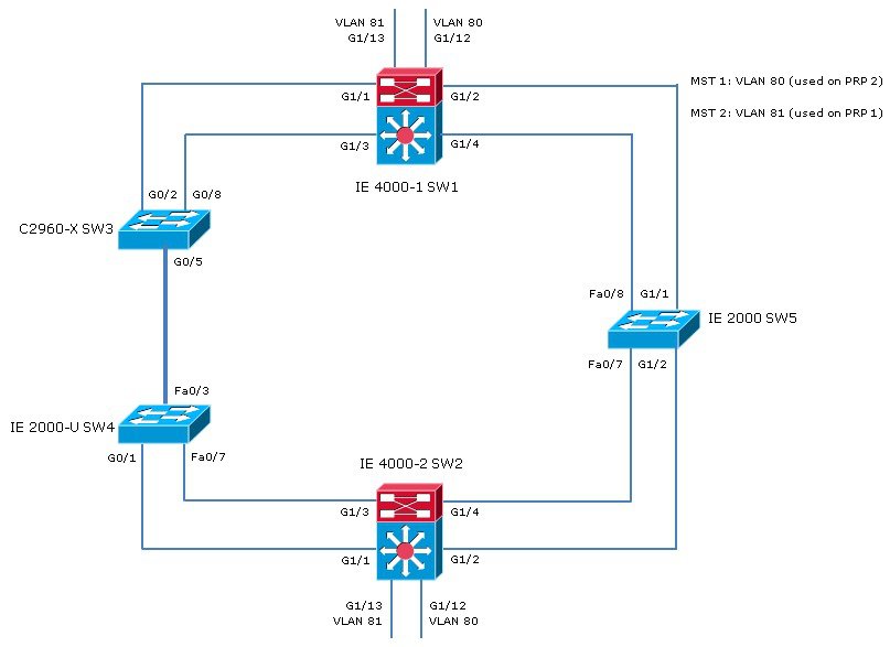
In this example, the configuration establishes two VLANs, 80 and 81, and the Spanning Tree Protocol is configured for each PRP channel on the VLANs, MST-PRP1 and MST-PRP2, respectively.
There are two IE 4000 switches within the topology, identified as switch 1 (SW1) and switch 2 (SW2).
The commands below show how to configure the Spanning Tree Protocol, VLANs, and PRP channels and groups on SW1:
spanning-tree mode mst spanning-tree extend system-id ! spanning-tree mst configuration instance 1 vlan 80 instance 2 vlan 81 vlan 80 name MST-PRP2 ! vlan 81 name MST-PRP1 ! interface PRP-channel1 switchport access vlan 81 switchport mode access spanning-tree bpdufilter enable spanning-tree portfast edge trunk ! interface PRP-channel2 switchport access vlan 80 switchport mode access spanning-tree bpdufilter enable spanning-tree portfast edge trunk ! interface GigabitEthernet1/1 switchport access vlan 81 switchport mode access media-type rj45 speed 100 prp-channel-group 1 ! interface GigabitEthernet1/2 switchport access vlan 81 switchport mode access media-type rj45 speed 100 prp-channel-group 1 ! interface GigabitEthernet1/3 switchport access vlan 80 switchport mode access media-type rj45 speed 100 prp-channel-group 2 ! interface GigabitEthernet1/4 switchport access vlan 80 switchport mode access media-type rj45 speed 100 prp-channel-group 2 interface GigabitEthernet1/9 switchport access vlan 81 switchport mode access ! interface GigabitEthernet1/10 no switchport ip address 192.168.100.222 255.255.255.0 shutdown ! interface GigabitEthernet1/11 switchport access vlan 80 switchport mode access ! interface GigabitEthernet1/12 switchport access vlan 80 switchport mode access ! interface GigabitEthernet1/13 switchport access vlan 81 switchport mode access ! interface Vlan80 ip address 10.208.80.111 255.255.255.0 ! interface Vlan81 ip address 10.208.81.111 255.255.255.0
The commands below show how to configure the Spanning Tree Protocol, VLANs, and PRP channels and groups on SW2:
spanning-tree mode mst spanning-tree extend system-id ! spanning-tree mst configuration instance 1 vlan 80 instance 2 vlan 81 ! ! interface PRP-channel1 switchport access vlan 81 switchport mode access spanning-tree bpdufilter enable spanning-tree portfast edge trunk ! interface PRP-channel2 switchport access vlan 80 switchport mode access spanning-tree bpdufilter enable spanning-tree portfast edge trunk ! interface GigabitEthernet1/1 switchport access vlan 81 switchport mode access media-type rj45 speed 100 prp-channel-group 1 ! interface GigabitEthernet1/2 switchport access vlan 81 switchport mode access media-type rj45 speed 100 prp-channel-group 1 interface GigabitEthernet1/3 switchport access vlan 80 switchport mode access media-type rj45 speed 100 prp-channel-group 2 interface GigabitEthernet1/4 switchport access vlan 80 switchport mode access media-type rj45 speed 100 prp-channel-group 2 interface GigabitEthernet1/9 switchport access vlan 81 switchport mode access interface GigabitEthernet1/10 no switchport ip address 192.168.100.223 255.255.255.0 shutdown ! interface GigabitEthernet1/11 switchport access vlan 80 switchport mode access ! interface GigabitEthernet1/12 switchport access vlan 80 switchport mode access interface GigabitEthernet1/13 switchport access vlan 81 switchport mode access interface Vlan80 ip address 10.208.80.222 255.255.255.0 ! interface Vlan81 ip address 10.208.81.222 255.255.255.0
The commands below show how to configure the Spanning Tree Protocol and VLANs on SW3:
spanning-tree mode mst spanning-tree extend system-id
spanning-tree mst configuration instance 1 vlan 80 instance 2 vlan 81 interface GigabitEthernet1/0/1 switchport access vlan 81 switchport mode access shutdown no mdix auto ! interface GigabitEthernet1/0/2 switchport access vlan 81 switchport mode access interface GigabitEthernet1/0/5 switchport trunk allowed vlan 20,80,81,88 switchport mode trunk interface GigabitEthernet1/0/8 switchport access vlan 80 switchport mode access
The commands below show how to configure the Spanning Tree Protocol and VLANs on SW4:
spanning-tree mode mst spanning-tree extend system-id ! spanning-tree mst configuration instance 1 vlan 80 instance 2 vlan 81 vlan 80 name MST-PRP2 vlan 81 name MST-PRP1 interface FastEthernet0/3 port-type nni switchport trunk allowed vlan 20,80,81,88 switchport mode trunk interface FastEthernet0/7 port-type nni switchport access vlan 80 ! interface FastEthernet0/8 port-type nni switchport access vlan 80 interface GigabitEthernet1/1 port-type nni switchport access vlan 81 interface GigabitEthernet1/2 port-type nni switchport access vlan 81
The commands below show how to configure the Spanning Tree Protocol and VLANs on SW5:
spanning-tree mode mst spanning-tree extend system-id spanning-tree mst configuration instance 1 vlan 80 instance 2 vlan 81 vlan 80 name MST-PRP2 vlan 81 name MST-PRP1 interface FastEthernet1/7 switchport access vlan 80 switchport mode access ip device tracking maximum 0 interface FastEthernet1/8 switchport access vlan 80 switchport mode access ip device tracking maximum 0 interface GigabitEthernet1/1 switchport access vlan 81 switchport mode access ip device tracking maximum 0 ! interface GigabitEthernet1/2 switchport access vlan 81 switchport mode access ip device tracking maximum 0
PRP is supported on IE 2000U, IE 4000, IE 4010, and IE 5000 switches. Not all versions of IE 2000U support the PRP feature, and not all industrial platforms support all features. The following table lists the PRP features supported by each platform.
Precision Time Protocol (PTP) over Parallel Redundancy Protocol (PRP)
Cisco IOS Release 15.2(6)E
Supported on IE 4000, IE 4010, and IE 5000.
Parallel Redundancy Protocol Enhancements (Supervisor frame/ Mixed traffic support )
Cisco IOS Release 15.2(5)E
Supported on IE 2000U, IE 4000, and IE 5000.
Parallel Redundancy Protocol including PRP mode LED.
Cisco IOS Release 15.2(4)EC
Initial support on IE 4010.
Cisco IOS Release 15.2(2)EB
Initial support on IE 5000.
Cisco IOS Release 15.2(2)EA
Initial support on IE 4000.
Parallel Redundancy Protocol
Cisco IOS Release 15.0(2)EK
Initial support on the following IE 2000U platforms: IE-2000U-8TC-G , IE-2000U-16TC-G, IE-2000U-16TC-GP, IE-2000U-16TC-G-X
6-port IE 2000U SKUs do not support the PRP feature.